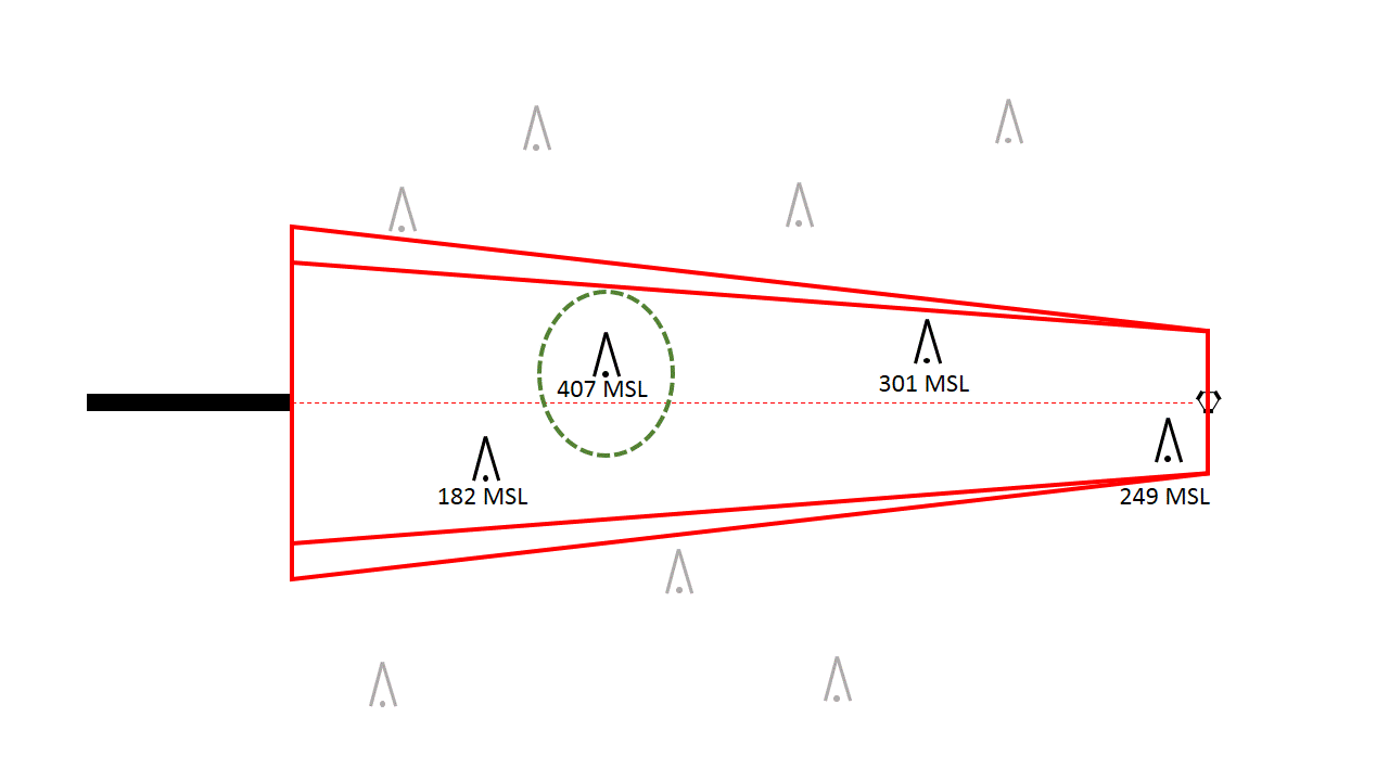
Let's take a basic VOR approach, for instance, with the VOR located exactly 5 nm from the runway and exactly on runway centerline:
With the VOR 5.0 nm from the runway threshold, it is perfectly located to serve as the Final Approach Fix, the FAF. So, we'd simply measure the final approach course. For this, all the calculations and measurements are done in True, not Magnetic. Then later when they're published, they are all converted to Magnetic. This is for ease of calculation and consistency.
Simple so far, but the next part is where some of the TERPS criteria and calculations come into play, where we establish the area the specialist will evaluate for obstacles. Every Private Pilot learns that a VOR radial gets "wider" the further you get from the VOR itself, so we have to account for that. Also, how precisely are you going to cross over that VOR on the way inbound? To allow for this, the area starts at 1.0 nm either side of centerline at the VOR, and gets wider the further you go. The formula for this is W = 2*(.05D+1) where D is the distance from the VOR in nautical miles, and W is the width, also in nautical miles. So at 5.0 nm, the total width is 2.5 nm, or 1.25 nm either side of centerline. This is called the "primary area". We'd draw this out like so (not to scale):
There is also a "secondary area" that exists outside of the primary area. For a VOR, it is determined by the formula W = .0333D. So at the VOR this secondary area is 0.0 nm wide, but at 5.0 nm from the VOR it is 0.17 nm, in addition to the width of the primary area. The difference between the primary and secondary area is the amount of obstacle clearance provided - in the primary it's a fixed amount, while in the secondary area it tapers from that fixed amount to 0 ft at the very outside edge (I'm not going to discuss that any more in this post though.)
Now that we have our obstacle evaluation area, we can look at the obstacle environment. "Obstacles" in this sense can mean many things: antenna towers and buildings are obvious, as are mountains and other terrain features. What about trees? Yep, those too. Some airports have roads running right next to the airport - the vehicles on those are obstacles as well. Windmills. Anything that could cause a hazard to aircraft. So an accurate database is important! In our example we find the following nearby obstacles:
Some are in our evaluation area, some are not. Without even caring how high they are yet, we can eliminate the ones that are not in our area, and look up how high the rest are:
Sure, the 182 MSL obstacle is closer to the runway, and the 249 MSL obstacle is right where the pilot begins descending. But the 407 MSL obstacle is the most important one, because it's the tallest. If we establish an MDA that will clear that obstacle, it will also clear all the other obstacles. So how much clearance do we provide?
This varies by type of approach and whether or not there is vertical guidance, but for non-precision approaches like VOR, the minimum Required Obstacle Clearance (ROC) is 250 feet. It can be greater in many instances, such as when a distant altimeter source is being used, or the accuracy of the obstacle survey is worse than standard. But with a minimum ROC of 250 feet, that means our MDA has to be at least 407 MSL + 250 ft = 657 MSL. MDAs are published in 20 foot increments, so we round up to 660 MSL, and that's what would be published! Note we always round up, never down, for safety.
One comment about that 250 ft obstacle clearance - that's close! If you look down and see an antenna tower just 250 feet below you, you'll know what I mean. Especially at night, that obstruction light at the top sure looks a lot closer than 250 feet. Couple that with altimeter error and allowance for non-standard low temperatures, and that's one of the reasons that on the instrument checkride, the Practical Test Standards say you can be 100 feet high but zero feet low at the MDA - you don't want to be low even a little bit!
Notice that the elevation of the runway hasn't entered into this calculation at all. Typically, the altitude of the runway isn't really a factor, unless it sits on top of a hill and is the highest thing around, becoming its own controlling obstacle! With our MDA of 660 MSL, the aircraft might be 300 ft above the runway, it might be 500, it could even be 1000 if the airport was below sea level like in Death Valley, California or some other places. That information is determined later in order to chart it, but it does not directly affect the MDA itself.
Now, this scenario was simple - a VOR conveniently positioned just where we needed the the FAF to be. It isn't often this simple. The VOR may be offset, or on the field, or there may be terrain in the way. GPS, of course, lends more flexibility to this process.
Other segments of the approach such as the intermediate and initial segments are evaluated similarly, just with differently-shaped evaluation areas and different minimum ROC values. Missed approach procedures and procedures with vertical guidance like an ILS follow some different rules due to the sloping evaluation surface that is necessary. Maybe I'll touch on those in a future post...
Good flying!


No comments:
Post a Comment