Sunday, March 30, 2014

How is an approach constructed? A very basic overview of final approach segments.

I've received a few questions along the lines of "basically, what goes into making an approach?"  So in this post, I'm going to try to go into the very basics of one step of the process, how the developer arrives at the altitude and heading for the final approach segment for a VOR approach.  Realize that this will be a very brief overview, that the full criteria that goes into designing a whole approach is a field full of numerous and complex rules, regulations, interpretations, and more.  I can only touch on some of the basic concepts in a blog format. Readers who are more knowledgeable about aspects of TERPS will detect some glaring omissions in this post - I know, I know. It was intentional for simplicity. The source for all of this is FAAO 8260.3B.

Let's take a basic VOR approach, for instance, with the VOR located exactly 5 nm from the runway and exactly on runway centerline:


With the VOR 5.0 nm from the runway threshold, it is perfectly located to serve as the Final Approach Fix, the FAF. So, we'd simply measure the final approach course.  For this, all the calculations and measurements are done in True, not Magnetic. Then later when they're published, they are all converted to Magnetic.  This is for ease of calculation and consistency.


Simple so far, but the next part is where some of the TERPS criteria and calculations come into play, where we establish the area the specialist will evaluate for obstacles. Every Private Pilot learns that a VOR radial gets "wider" the further you get from the VOR itself, so we have to account for that. Also, how precisely are you going to cross over that VOR on the way inbound? To allow for this, the area starts at 1.0 nm either side of centerline at the VOR, and gets wider the further you go. The formula for this is W = 2*(.05D+1) where D is the distance from the VOR in nautical miles, and W is the width, also in nautical miles.  So at 5.0 nm, the total width is 2.5 nm, or 1.25 nm either side of centerline. This is called the "primary area". We'd draw this out like so (not to scale):


There is also a "secondary area" that exists outside of the primary area. For a VOR, it is determined by the formula W = .0333D. So at the VOR this secondary area is 0.0 nm wide, but at 5.0 nm from the VOR it is 0.17 nm, in addition to the width of the primary area. The difference between the primary and secondary area is the amount of obstacle clearance provided - in the primary it's a fixed amount, while in the secondary area it tapers from that fixed amount to 0 ft at the very outside edge (I'm not going to discuss that any more in this post though.)


Now that we have our obstacle evaluation area, we can look at the obstacle environment. "Obstacles" in this sense can mean many things: antenna towers and buildings are obvious, as are mountains and other terrain features. What about trees?  Yep, those too. Some airports have roads running right next to the airport - the vehicles on those are obstacles as well.  Windmills.  Anything that could cause a hazard to aircraft. So an accurate database is important! In our example we find the following nearby obstacles:


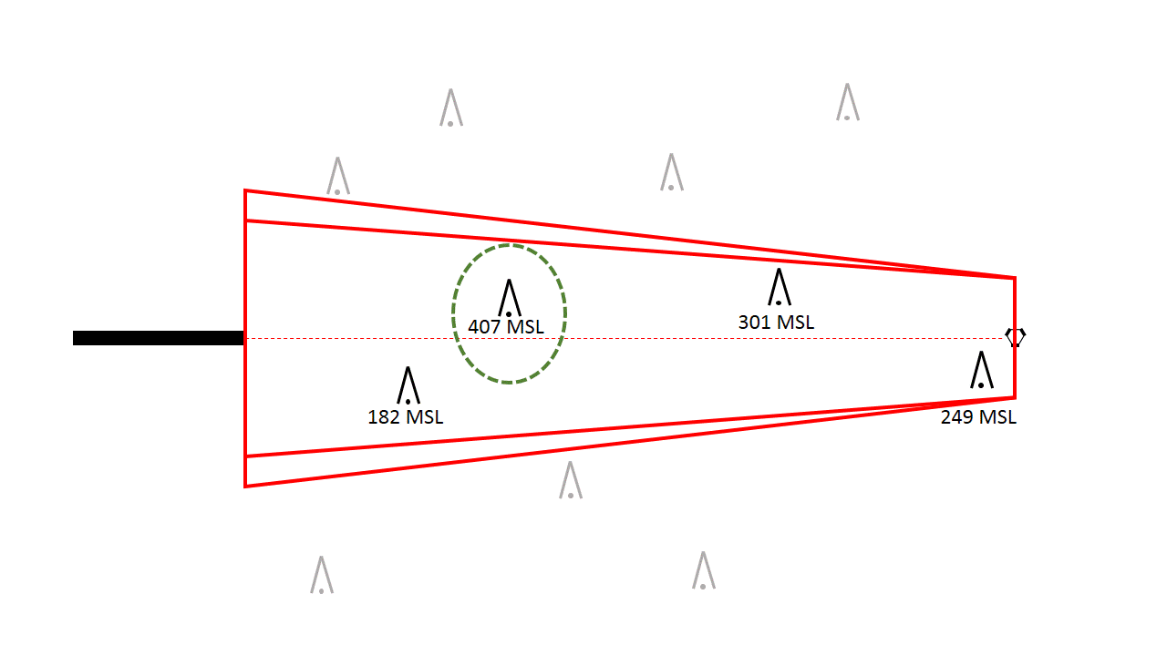
Some are in our evaluation area, some are not. Without even caring how high they are yet, we can eliminate the ones that are not in our area, and look up how high the rest are:


Almost there! On a non-precision approach like a VOR - one that does not provide for vertical guidance - the pilot will cross the FAF and begin descent to some minimum altitude that is specified - the Minimum Descent Altitude, or MDA - then level off until reaching the Missed Approach Point or seeing the runway and landing. How fast will the pilot descend? At what point on final will the aircraft reach the MDA? We don't know - it depends of course on descent rate and ground speed. All we know is that somewhere between the FAF and the runway, we have to establish a minimum altitude below which the pilot cannot descend. The pilot might be aggressive and descend quickly so the aircraft reaches the MDA just after the FAF, or the aircraft might reach it right before the runway. So, simply, we select the tallest obstruction in the area and it becomes our "controlling obstacle". In our case, it's that 407 MSL obstacle:


Sure, the 182 MSL obstacle is closer to the runway, and the 249 MSL obstacle is right where the pilot begins descending. But the 407 MSL obstacle is the most important one, because it's the tallest. If we establish an MDA that will clear that obstacle, it will also clear all the other obstacles. So how much clearance do we provide?

This varies by type of approach and whether or not there is vertical guidance, but for non-precision approaches like VOR, the minimum Required Obstacle Clearance (ROC) is 250 feet. It can be greater in many instances, such as when a distant altimeter source is being used, or the accuracy of the obstacle survey is worse than standard. But with a minimum ROC of 250 feet, that means our MDA has to be at least 407 MSL + 250 ft = 657 MSL. MDAs are published in 20 foot increments, so we round up to 660 MSL, and that's what would be published! Note we always round up, never down, for safety.

One comment about that 250 ft obstacle clearance - that's close! If you look down and see an antenna tower just 250 feet below you, you'll know what I mean. Especially at night, that obstruction light at the top sure looks a lot closer than 250 feet. Couple that with altimeter error and allowance for non-standard low temperatures, and that's one of the reasons that on the instrument checkride, the Practical Test Standards say you can be 100 feet high but zero feet low at the MDA - you don't want to be low even a little bit!

Notice that the elevation of the runway hasn't entered into this calculation at all.  Typically, the altitude of the runway isn't really a factor, unless it sits on top of a hill and is the highest thing around, becoming its own controlling obstacle! With our MDA of 660 MSL, the aircraft might be 300 ft above the runway, it might be 500, it could even be 1000 if the airport was below sea level like in Death Valley, California or some other places. That information is determined later in order to chart it, but it does not directly affect the MDA itself.

Now, this scenario was simple - a VOR conveniently positioned just where we needed the the FAF to be. It isn't often this simple.  The VOR may be offset, or on the field, or there may be terrain in the way. GPS, of course, lends more flexibility to this process.

Other segments of the approach such as the intermediate and initial segments are evaluated similarly, just with differently-shaped evaluation areas and different minimum ROC values. Missed approach procedures and procedures with vertical guidance like an ILS follow some different rules due to the sloping evaluation surface that is necessary. Maybe I'll touch on those in a future post...

Good flying!

Tuesday, March 18, 2014

ILS intermediate stepdown fixes and HIGH temperature - be careful!

A few posts ago I talked about the effects of low temperature on minimum altitudes.  Since lower than standard temperature means you are lower than your altimeter shows, it can be a real problem in some areas.  But the opposite effect can also be true - being HIGHER than you think.  How could that be a problem?  Well, it could result in a steeper than normal descent to the runway, but a fairly common situation where it has caused problems is on an ILS.

This came up during a recent IFR instructional flight.  My student was cleared to "maintain at or above 3000 until established on the localizer, cleared localizer XX approach."  He intercepted, and when I reminded him that the published altitude for the intermediate segment (and glideslope intercept) was at 2600, not 3000, so he should descend, he asked me why can't he intercept the glideslope at 3000?  For the time being, "because I told you so" had to be sufficient, but clearly he wasn't satisfied with that answer for long after we landed!

There are a variety of reasons why it's best to intercept the glideslope at the published altitude, but the one I want to discuss here is the effect of high temperature on indicated altitude when on glideslope.  The potential problem isn't from the FAF inbound, it's prior to the FAF.

Many ILS approaches have stepdown fixes in the intermediate segment prior to the FAF.  A pilot is, of course, responsible to not descend below those minimum altitudes until crossing the respective fixes.  What if the pilot intercepts the glideslope well before (and therefore well above) the FAF and published glideslope intercept altitude and follows it down?  Will the aircraft meet all the stepdown fix crossing restrictions until getting to the FAF?  Does it have to?  Let's look at an example, KLAX ILS OR LOC RWY 25L:

KLAX ILS OR LOC RWY 25L

I've only included the profile view because it's the only part that's pertinent to this discussion.  

Notice all the stepdown fixes before the FAF. If you do the math, the HUNDA and GAATE fixes are just about right on glideslope (the profile views are not to scale, so it doesn't look it), whereas FUELR at 7000 is below glideslope.  If you pass FUELR at 7000 and stay there waiting to intercept the glideslope, then follow it down, normally you'd do fine and clear GAATE and HUNDA right on altitude. 

But I said I was going to talk about non-standard HIGH temperatures, didn't I?  This can take a bit of mental gymnastics...

So, remember that the glideslope is for all useful purposes a fixed line in space.  It is not affected by pressure or temperature, it's an electronic beam. But our altimeters are affected by temperature and pressure.  We adjust for pressure by changing the altimeter setting, but we don't adjust for non-standard temperature at all. And if we don't, then a higher-than-standard temperature will cause our altimeter to read lower than we actually are - or in other words we are higher than we think we are.  Normally this is okay - it means more separation above terrain for one, and since everybody is using the same altimeter setting, it causes no problems with conflicting traffic either.

But back to that electronic beam that we know and love called the glideslope.  It's fixed in space.  If we cross GAATE on glideslope, we will be right at 5000, true altitude. What will our altimeter show? 4900? 4800? Depends on the difference from standard temperature. So when we cross GAATE on glideslope, if our indicated alitude is 4900, then guess what?  We just busted our minimum altitude! 

Okay, so, is this actually a problem? Well, at an airport in busy airspace like LAX, it proved to be.  They have multiple traffic corridors both above and especially below some of these fixes going into other airports. If that crossing traffic is flying at the correct indicated altitude, it is (due to the temperature effects) also higher than indicated.  But since you are maintaining that glideslope and therefore indicating a hundred feet lower than the stepdown fix altitude, you have just caused a loss of required separation!

This actually caused a problem a few years ago and they had many pilot violations as a result (see links at the end of this post). It was a real problem, because some pilots didn't realize they wouldn't meet the stepdown restrictions if they intercepted the glideslope at a higher altitude prior to the FAF and followed it on down. 

(Notice that this doesn't apply to stepdowns in final, of course they're marked "LOC only" anyway, like LADLE on the example above.  Only to stepdown fixes prior to the FAF.)

Here's what the NBAA has to say about it:

And here's the release from the FAA:

Fly safe and watch those intermediate segment stepdown fixes!

Tuesday, March 11, 2014

Alternate missed approach holding? What is that?

Ever look at an approach chart and see TWO missed approach holding patterns depicted? How about this example from Seattle, Washington (KSEA) ILS OR LOC RWY 16L?  Or Norman, Oklahoma (KOUN) ILS OR LOC RWY 17? Maybe Moses Lake, Washington (KMWH) ILS OR LOC RWY 32R?

KSEA ILS OR LOC RWY 16L
 
KOUN ILS OR LOC RWY 17

KMWH ILS OR LOC RWY 32R

All of these have missed approach instructions (not shown in the excerpts above) that take you to the primary missed approach holding fix. But NONE of them tell you how to get to the alternate missed approach holding fix, or why you would use it, or when! So what are these for?

Imagine you're flying the ILS at SEA. The SEA VORTAC happens to be out of service, but that doesn't really matter for your ILS, does it? Not for final anyway. So you can fly the procedure just fine up until the missed approach point without needing the SEA VORTAC. However, if the SEA VORTAC is out of service, what then? You can't fly the missed approach procedure – after all, it depends on navigating via the SEA R-161 to MILLT intersection/DME fix. Since a clearance to fly the approach includes a clearance to fly the missed approach if necessary (unless ATC gives you different missed approach instructions), if the SEA VORTAC is out of service, you really couldn't fly the approach. So an alternate missed approach holding pattern is established, in this case at the TCM VORTAC.

Notice that while the alternate missed approach holding pattern is shown, how to get there is not! This is almost solely for chart clutter and readability reasons - you wouldn't want to follow the wrong missed approach by mistake. If you need to fly the alternate missed approach, ATC will tell you how to get there and at what altitude. The FAA evaluates these alternate missed approach procedures just like the primary ones, they just don’t put them on the chart.

Similarly, the OUN example above has holding based off the IRW VORTAC. If it's out of service, you hold at the OUN NDB. For MWH, instead of using a radial off the MWH VORTAC, you'd head to the EPH VORTAC.

You’ll see these most often on ILS procedures, since they usually have holding based off another NAVAID. Conversely, many VOR approaches use the same VOR for holding that they used for the final approach – so if it’s out of service, you’re not going to be able to fly the approach anyway. However, occasionally you do see alternate missed approach procedures on VOR approaches. You will never see them on GPS approaches, since if you don’t have GPS coverage, you’re not going to get that far to begin with!

Now, understand these are all backup plans. And not all of them are usable by all aircraft. For example, the alternate missed approach at OUN isn't usable if you only have VOR receivers on board. But if this is the case, just inform ATC and ask for something different.

However, as you look through various procedures, you will find some that look like they should have an alternate missed approach hold charted, but don’t.  This is often simply an issue of practicality. Sometimes ATC facilities request that there not be an alternate missed procedure for a certain airport, sometimes there is no alternate facility to use, sometimes the procedure has “RADAR REQUIRED” to enter the procedure anyway (so you know the missed would certainly be radar vectors), or some other considerations.

But if you see a missed approach holding pattern depicted out there all alone with no obvious way to get to it, now you know what it’s there for!


Tuesday, March 4, 2014

Holding pattern orientation and circling naming conventions

I received a great e-mail from a listener to the interview in San Diego.  As I write this it's 9 degrees (F) here in Dayton, Ohio, so I'm wishing I was in San Diego!

He asks the following:

First, I fly around San Diego and it seems most published missed approach holds require a parallel/teardrop entry.  Why are they not designed for a direct entry?

Second, The city of San Diego has multiple airports, KSAN, KSEE, KMYF, KSDM. KSEE has a LOC-D approach.  The -D signifies it's the fourth LOC approach. My question is whether it's the fourth LOC approach into KSEE, or is it the fourth LOC approach for the city of San Diego?

Wouldn't it be nice if all holds were a direct entry?  Sure would, but that hardly ever seems to be the case, doesn't it?

There are several considerations when designing missed approach holding patterns (roughly in priority order, though this is not found in the regulations):
1. Signal reception for course guidance and crossing radials (if applicable).
2. Surrounding terrain (usually the most critical consideration).
3. Surrounding airspace.
4. ATC procedures/traffic flow/sector boundaries.
5. Ease of flying another procedure once in the holding pattern.
6. Existence of already-established holding patterns at the same fix.
7. Ease of entry into the holding pattern.

1-4 are fairly self-explanatory.  For #5, there is a pertinent requirement in the regulations (FAA 8260.3B, para 291): 

"Whenever practical, holding patterns should be aligned to coincide with the flight course to be flown after leaving the holding fix".  

I consider this the "what are you going to do next" clause.  So you're in holding, but you don't want to stay there forever.  It's nice if the inbound course for the hold lines up with, say, another (or even the same) approach procedure.  For example, many RNAV (GPS) approaches have the missed approach go to the IF for the RNAV (GPS) approach to the opposite runway.  The holding pattern will often be oriented so that once established, you could fly the opposite approach from that point. 

Case in point - KOJA (Weatherford, OK), RNAV (GPS) RWY 17 and 35.  Fly one, go missed to the IF for the other one, turn around and repeat. You can see-saw back and forth all day flying one procedure after the other if you like.


Many ILS and LOC procedures have the missed approach take you back to the FAF and hold, perfectly lined up for another try. 


The same is often true of VOR approaches where the VOR is the FAF. Sometimes, though, especially in mountainous areas, holding patterns just appear cockeyed for no reason.  Often in these situations, terrain forces the orientation - just a few degrees one way or the other may make all the difference in the holding pattern altitude.

For reason #6 above, a good example is if the holding is at a VOR, there may already be other holding patterns at that fix - to reduce confusion, any new patterns may be oriented the same direction.  Or they may not - depends on the exact situation. 

Notice that "ease of entry" is typically the last consideration.  This reflects the reality that holding procedures just aren't flown much on non-training flights - ATC will more typically issue its own set of missed approach instructions, usually using radar vectors.  Also, since it has to be presumed that IFR pilots are capable of flying any type of hold entry, the importance of this consideration is reduced to a "nice, but not necessary" level.

An additional note on this - holding patterns are BIG when compared to the speeds we typically fly in IFR training.  A Cessna 172 flying a 1-minute holding pattern in no wind will generally stay within about 2 nm of the fix at all times, even allowing for turns.  Holding pattern airspace increases with altitude, but the smallest holding patterns in use by the FAA are ovals about 14.4 nm long and 8.8 nm wide, with an additional 2 nm buffer area on all sides!  This size is required to contain faster aircraft with correspondingly larger turn radii.  So even though the pattern might look like it's well clear of obstacles/airspace/traffic flow, it might not be for all aircraft.

For the second question, there are two rules in effect here, from FAAO 8260.19F, para 4-1-5f:

(1) Do not duplicate the alphabetical suffix for circling procedures at an individual airport to identify more than one circling procedure. If more than one circling procedure exists, and regardless of the final approach alignment or type of facility, use successive suffixes.

Example:
NDB-A, VOR-B, LDA-C

(2) The alphabetical suffix for circling procedures must not be duplicated at airports with identical city names within one state. Regardless of the airport name, successive suffixes must be used for all airports that serve the same city.

There is another clause in FAAO 8260.3B, para 162:

"a revised procedure will bear its original indentification".

Presumably, at least at one time there were already -A, -B, and -C circling procedures to airports serving San Diego, so the KSEE LOC circling was labeled the LOC-D.  I cannot find a -B or -C at any of the civilian airports, but given the rule above, it's likely there were at one time. Once the KSEE LOC-D was named, any further amendments are supposed to keep that name, to reduce confusion.

Thanks for the great questions!