Thursday, November 13, 2014

"Diverse Departure" procedures

I've written about various types of departure procedures before - VCOAs here and the option for Part 91 operators to take off in "0/0" conditions here.

But I recently received some questions from a friend and reader based on a recent flight of his from Denton, Texas to McAlester, Oklahoma (MLC) and returning, which you can read about on his blog at pilottangocharlie.blogspot.com. After stopping at MLC, he got his clearance which consisted of the MLC VOR as the first fix. There were some real instrument conditions around, so this was a for-real instrument departure. But the only departure "procedure" that is published for MLC is a set of takeoff minimums. He realized this situation wasn't covered real well in his instrument training, and needed a little refresher on how this works.

I can sympathize! My instrument training was in southeast coastal Virginia, where the flat terrain makes Obstacle Departure Procedures (ODP's) purely an academic exercise for the most part. Add in that radar coverage was excellent and most IFR releases simply started with "Fly runway heading..." and the result was that ODPs were not covered very well during my IFR training (in fact, they may not have been covered at all). In my experience this is pretty common, which is unfortunate because every flight starts with a departure!

McAlester actually has a good example of a basic textual obstacle departure procedure (or lack thereof):


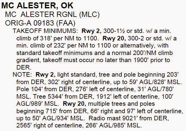
From Runway 2 it has a pretty typical set of takeoff minimums or a minimum climb gradient. This situation I covered in my "0/0" article, so I won't go into it here. But remember that while these takeoff minimums aren't required for Part 91 operations, they are a REALLY good idea.

From Runway 20 there are the same two options, plus a third new one - the option to reduce takeoff distance by 1900 feet. This allows the airplane to climb at a standard rate and still clear the nearby obstacle with an acceptable safety margin. Obviously you would have to carefully plan to make sure your airplane, on that day, given those weather conditions and loading, can be off the ground by then. Seems like a small additional amount of safety factor, and it is, but the reason for the shorter takeoff roll option is just because some obstacle just barely penetrated the clearance surface and this slight reduction resolves it.


This is a good time to note the "cross departure end of the runway at least 35 feet AGL" wording in various training and reference publications. This requirement has been removed from the TERPS - the procedure design standards - but is still referenced in many FAA publications, such as the Aeronautical Information Manual, para 5-2-8b1 and the Instrument Procedures Handbook, page 1-14. Both of these say substantially the same thing:

"...required obstacle clearance for all departures, including diverse, is based on the pilot crossing the departure end of the runway at least 35 feet above the departure end of runway elevation..."

Which, while a good idea from a safety perspective, is not technically accurate any longer. I believe the issue was one of planning - how do you determine whether you can cross the departure end 35 feet high? Many light aircraft performance charts give a 50-foot figure, but how do you extrapolate? So the standards were revised to the easier-to-determine method of just getting airborne by the end of the runway, unless otherwise specified.

Okay, so you took off, but now what?

In the MLC example, he was departing from runway 2, but the first fix in his clearance was the MLC VOR to the south - behind him. How to go about getting there?


In the absence of a departure procedure or specific ATC instructions, the short answer is "however you want" (within reason of course). There are only a couple of restrictions, both spelled out in the same AIM paragraph linked above:

1. You climb on runway heading to 400 AGL before turning.
2. You keep climbing at the standard rate (200 feet per nm) or as specified in the takeoff minimums up to your cleared altitude.

So in this case, the way to go would be to climb straight ahead to a comfortable altitude, then turn direct to the VOR and proceed on your cleared route. Depending on the ceiling and visibility, I might not turn all the way around at 400 feet, though it should be safe to do so - a little more altitude might be prudent in low IMC, plus it allows a little more time to get turned around and tracking direct to the VOR, which is still very close behind you.

This is what's known as a "diverse departure". "Diverse" in this sense meaning "any direction", as there are no restrictions placed on the pilot as far as routing goes. In non-mountainous areas of the country like McAlester, Oklahoma, the safety of a "200 feet per nm" climb gradient is evaluated out to 25 nm from the airport. In mountainous areas, it's 46 nm. This is almost always enough to get you on a published airway, above the OROCA, or into radar contact. And if you're wondering what the definition of "mountainous area" is, the FAA defines that as well in 14 CFR 95.

The map of the continental U.S. leads to some humorous observations, like Scottsbluff, NE being considered mountainous. I suppose they had to draw a line somewhere!


The great thing about takeoff minimums and departure procedures is that you can always (and should always) review them, on the ground, before even getting in the airplane. Once in flight you may have to land at an unplanned airport, but I haven't yet heard of the takeoff happening at a different airport!


Wednesday, October 29, 2014

TAA's and ILSes (and other acronyms!)

Be ready for a few acronyms!

The FAA has recently begun adding GPS routes into ILS procedures, which in my opinion is a great thing! This combination of GPS and ground-based navigation allows for more flexibility for routing and easier flyability among other benefits. Here's what I'm talking about, see this example at Statesville, NC (KSVH).


If you're not familiar with TAA's (Terminal Arrival Areas), they are on many RNAV (GPS) approaches already but are just now being added to ground-based approaches as well:


TAA's allow you to be cleared for the approach anywhere within the depicted area, usually within 30nm of the fix shown (in this case PEGTE). The minimum altitude you must be at depends on distance and what your course is to that fix. So, in this example, coming from the west the minimum altitude is 4300 until within 6 nm of PEGTE, then 3400. From the east it's simpler, just 3400 all the way to PEGTE. Also notice that any course to the fix from 195 clockwise to 015 is considered a "NoPT" segment, so you can skip the depicted Hold-in-lieu-of-Procedure-Turn (HILPT). From the western half of the TAA you are still required to execute the HILPT in the example.

Another benefit of the TAA is that they do not require a VOR-based route into the procedure. Notice that the IF, PEGTE, is not anywhere on the Low Enroute chart (though there are some crossing radials, it's not on an airway). The TAA gives you the flexibility to be on a published segment of the approach, flying direct to PEGTE from anywhere within 30nm.


Another example is that at Rock Hill, SC (KUZA).


This one has a complete "T" setup of IAFs and the TAA to match. Unlike at KSVH, this allow you to come from essentially any direction and avoid flying the HILPT. If you're coming from the northwest, you'd fly direct to GUCRE, then be on a NoPT segment after reaching GUCRE headed to CONEL. The same idea with TAGCU from the northeast. From the south, you'd fly to CONEL and then proceed straight-in after reaching it.

One caution - if like in many airplanes, you're displaying both your GPS and ILS guidance on the same CDI, make sure to switch the CDI source as you reach the IF.

Another great benefit of a TAA is that ATC can clear you for the approach from a long way away. In order for ATC to clear you for the approach, you are required to either be on radar vectors OR established on a published segment of that approach. Since being within the TAA is considered to be on a published segment of the approach, you might be 28nm from GUCRE and hear a very simple "N123, Cleared ILS Y runway 2 approach"!

Now, many of these TAA-to-ILS approaches probably also have an RNAV (GPS) approach to the same runway with LPV minimums. In that case, if you have a WAAS-equipped GPS receiver, you'd probably just fly the GPS approach. But sometimes the minimums aren't quite the same, or there isn't an LPV approach to that runway for various reasons, so the TAA-to-ILS might be a benefit even with a WAAS receiver. If you AREN'T WAAS equipped, then the TAA-to-ILS is great, because it doesn't take a WAAS receiver to fly it!

For more about TAA's themselves, please see BruceAir's great blog post about them here. Highly recommended reading!

I expect to see more and more of these published as time goes on. Let me know if you see a new one!

(Acronym count: 12. I guess that's not too bad.)

Monday, September 22, 2014

Feeder routes to procedure turns - don't make up your own!

There has been a very active discussion occurring on the Pilots of America web board the last couple of weeks regarding a Hold-in-Lieu-of-Procedure-Turn (hereafter HILPT) published on an approach chart in southern Oklahoma. Sadly, as is the case with many online forums, the discussion has degraded into name-calling, insults and other unproductive and uneducational matters. So I'll try to break it down here.

The approach in question is the Durant, OK (KDUA) VOR/DME RWY 35. 


Notice there is one published way for a non-GPS-equipped aircraft to enter this procedure without receiving radar vectors to final. That aircraft would start at the BYP VORTAC IAF, fly the BYP-321 radial until HANOM, turn right, then proceed inbound to the URH VOR/DME on the URH-184 radial. There is a HILPT published at HANOM, but since the route from BYP is labeled NoPT, you would not fly the HILPT coming from that direction.

Well, then from what direction DO you fly the HILPT?

Seems like an easy answer, that you'd fly the HILPT if you were coming at the approach from the north - you'd fly to the URH VOR/DME, then outbound on the 184 radial to HANOM, execute the HILPT and proceed inbound. Except it's not quite that easy, for one main reason:

There is no published segment from URH to HANOM.

Sure, there's a published route from HANOM to URH, but that's not the same thing. A route from URH to HANOM would be properly identified by a thin line as a feeder route. Note that the indication "R-184" below the HILPT does not indicate a route, it is simply showing what radial the final approach course is on. A route would be indicated by an altitude, a course, and a distance. So what is missing here is a charted, evaluated, and published route from URH to HANOM. Note that courses on instrument approaches are one-way, not two-ways like on most airways, and aren't meant to be flown backwards. This is why each segment of an approach has a directional arrow.

This is especially confusing because the URH VOR/DME is right on an airway - V63 - so it would be a logical place to have a feeder. Would it be possible to fly that route, from URH to HANOM and turn around? Of course - any instrument pilot should be able to do it with no problem. But from the way this procedure is charted, that exact route has not been evaluated for obstacles, even though the route the other way has been (the intermediate and final segments).

Why does this matter? It seems from looking at it that flying from URH to HANOM at an altitude of, say 2500 should work just fine. The reason has mainly to do with the difference in size of the areas evaluated by TERPS for intermediate and final segments versus a feeder route; the area evaluated for a VOR final being much narrower than for a feeder route. (At the VOR, the final is 1nm each side of center, whereas the feeder is 4nm each side of center, not considering what are known as "secondary areas" (see my 3/30/14 blog post for more about secondary areas.)

Let's say you're approaching the VOR in such a way that you need to make a 90 degree turn to go outbound on the uncharted "feeder" route from URH to HANOM. An actual feeder route, being wider, allows for you crossing the VOR, then beginning your turn, with enough area to contain the turn radius. A final segment used in reverse would not have this, as the area is much smaller (and turns to line up on final are much more restricted in terms of heading change for this reason). Might not be a problem in a 172, but in something faster it could. What if there is an antenna tower or mountain off to the side of final?

Sometimes a picture is worth more than 1000 words. This is probably such a situation:


This diagram shows a notional view of the areas evaluated for this approach. Since the area from HANOM to URH has been evaluated as a final approach segment, it's pretty narrow. But if an aircraft inbound from the east crossed the VOR and made a turn to proceed outbound on the final approach course, it could easily exceed the boundaries of the evaluated area. At 150 knots, a standard-rate turn results in a turn radius of about 0.8 nm. The final approach area is only 1.0 nm wide at the VOR, so while it seems to fit, that's only in an ideal situation. Adding in a tailwind that will increase turn radius, a slightly delayed start of the turn, and imperfect pilot technique means you rapidly run out of safety margin. What's outside of that area? Could be an antenna tower, could be a mountain, or it could be level terrain as far as the eye can see. There's no telling, but the published altitude doesn't reflect that because it wasn't part of the evaluation.

Compare that to the case if a feeder route was published from URH to HANOM. The feeder route, being much wider for exactly this reason, easily accommodates the turn radius:


So, if we can't fly from URH to HANOM for the HILPT, and if the only published route from BYP to HANOM is a NoPT segment, what's the purpose of the HILPT in the first place? There is none. I speculate that the HILPT is charted correctly, but that a feeder was erroneously left off during publication. This has been brought to the FAA's attention, so it will be interesting to see their response.

An example of a similar procedure that has the feeder and the Procedure Turn (though not a HILPT) charted is the Springfield, OH VOR RWY 24. Notice the thin line from the SGH VOR labeled "300 to OHMEE, 055 deg, (6.4)". It has all the necessary data to serve as a feeder route and has been evaluated and charted. Thanks to a blog reader (and former student) for providing this example!


Instrument approach procedures exist to keep us all safe, but we can't "roll our own". If something doesn't seem right or there appears to be an error, we need to bring it up to the attention of the FAA - don't just assume!

Saturday, September 6, 2014

IFR departures - Visual Climb Over Airport?

"For Climb in Visual Conditions...." wait, aren't I IFR?

Ever see these words on an instrument departure procedure and wondered what they mean? There's a little-taught (and probably even lesser flown) type of instrument departure procedure called a VCOA - Visual Climb Over Airport. I know it wasn't covered at all in my instrument training - of course that was in coastal Virginia, so with the terrain being very flat there wasn't much in the way of actual departure procedures to fly anyway.

So what is this? It's an instrument departure, but involves a VISUAL climb to an altitude at which you can then proceed into IMC along your cleared route. Kind of the opposite of a visual approach in that regard, and typically would only be used in an area without radar coverage. When this is an option, you will see it in either the takeoff minimums/textual departure procedure listing at the front of the approach chart book, or in the takeoff minimums section of a graphic obstacle DP, and it looks something like this:


These VCOA procedures are only published when there is an obstacle greater than 3 sm from the airport that causes a required climb gradient of greater than 200 ft per nm to clear. Here's what the FAA's Instrument Procedure Handbook has to say about them (page 1-38):

Visual Climb Over Airport (VCOA)
A visual climb over airport (VCOA) is a departure option for an IFR aircraft, operating in VMC equal to or greater than the specified visibility and ceiling, to visually conduct climbing turns over the airport to the published "climb-to" altitude from which to proceed with the instrument portion of the departure. A VCOA is a departure option developed when obstacles farther than 3 SM from the airport require a CG of more than 200 FPNM.

These procedures are published in the Take-Off Minimums and (Obstacle) Departure Procedures section of the TPP. [Figure 1-36] Prior to departure, pilots are required to notify ATC when executing the VCOA.

Okay, so there's a specified ceiling and visibility requirement for this VCOA. The intent is for the pilot to take off, spiral up over the airport until reaching a certain altitude, and then it's safe to fly the cleared route even if entering IMC at that point, assuming the climb continues to an appropriate altitude in the clearance. In our example from California, you would make gradual, climbing turns up to 8300 MSL (3400 AGL) and then continue climbing on your cleared route.

At first glance, that almost seems a little silly, doesn't it? The required ceiling is 3500 AGL, and that's pretty solid VFR, so why not just depart VFR? However, the threat that the procedure is designed to avoid is really those times when the ceiling is high enough over the airport, but obstacles (like mountaintops) are still obscured by cloud. This is reflected in the design methods for these procedures.

Briefly, a "cylinder" of airspace is evaluated around the airport, with a radius determined by the elevation (higher elevations needing a greater turn radius due to increasing TAS). In our example, the radius used is 3.4 nm (source - FAAO 8260.3B, Vol 4, Chapter 4).


The highest obstacle in this cylinder is used to establish the "climb-to" altitude. If there are other obstacles outside the cylinder, a 40:1 slope is then evaluated to see if it clears the obstacles. If it does not, then the "climb-to" altitude is increased appropriately. Notice that the "climb-to" altitude also provides for a minimum of 250 feet of obstacle clearance, growing as you get further from the cylinder.


A VCOA can also have a "route" attached to it, like at Craig, Colorado (CAG), where you would climb up over the airport then proceed on a radial to the nearby VOR. This departure procedure also incorporates a "normal" departure if you can make the climb gradient (of 510 ft per nm off runway 7!) but the parts we're interested contain the words "for climb in visual conditions".


This is a pretty complicated textual departure procedure, so it definitely takes some review before takeoff! Note that once you get to the VOR, you're not done - you need to follow the "thence ..." instructions in the last paragraph, which can consist of a climb in a holding pattern depending on your route of flight.

Certainly if you need to execute a maneuver like this it's important to inform ATC when you get your clearance so everybody knows what you're doing and there are no surprises. But flying them is admittedly pretty rare, so let me know how it went if you have actually flown one!

Thursday, August 14, 2014

RNAV (GPS) approaches - what happened to LNAV+V?

(8/18/14 update - looks like I was incorrect regarding the Garmin 430W/530W and LP+V! As of software revision 5.1, released in April 2014, these WAAS receivers now support LP+V. However, it looks like the Garmin 650/750 do not, at least as of software revision 5.0 which is the most current for them. Hopefully soon!)

Like my last article, this one comes from a question posed at a seminar at Oshkosh, where I was in the audience but was fortunately able to help answer the question.

The question pertained to RNAV (GPS) approaches with an "LP" line of minima, and was, in essence, "Why don't we get an advisory glideslope when conducting an LP approach, like we do when flying an LNAV approach?"

A little background (but brief, I don't want to get too much into types of RNAV minimums in this article).

The most basic line of RNAV (GPS) minimums is the "LNAV" line, meaning "Lateral Navigation". There is no vertical guidance, it's like a VOR approach, and can be flown without WAAS. GPS manufacturers thought that, if you had WAAS, it would be helpful to include an "advisory" glideslope to help make a nice, stabilized descent instead of the "dive and drive" that non-precision approaches typically resulted in. This was termed "LNAV+V" to show that an advisory glideslope was available and could be used for situational awareness.

However, this "advisory" glideslope was NOT evaluated by the FAA, and the pilot had to make sure to still comply with all pertinent altitude restrictions, to include leveling off at the MDA and going missed as appropriate. There was nothing depicted on the approach chart, because this capability was provided by the manufacturer, not the FAA.

Compare this to the LNAV/VNAV line of minimums. LNAV/VNAV minimums and glideslope ARE evaluated by the FAA for obstacle clearance and all the other factors, and they are flown to a DA like an ILS, meaning you don't have to level off at the DA, you just need to start your missed approach at that point.

When LNAV/VNAV minimums were published on the same chart as LNAV minimums, though, it could get a little confusing. For example, a Garmin 430W would annunciate the two, respectively, as "L/VNAV" and "LNAV+V". This is a little too easy to confuse if you don't look at it closely. Kind of reminds me of a cartoon of someone trying to fool the police with a license plate that is something like "8BB8B8" or "I1II1I1"!

Garmin 430W LNAV+V annunciation
This has actually been the source of some confusion throughout the pilot community. I've seen the questions - "My GPS says LNAV+V, does that mean I fly to the LNAV/VNAV minimums?" (no) or "If I'm flying LNAV+V, do I need to comply with the stepdown fix altitudes in final?" (yes).

Although more training could resolve this confusion, there is also a "human factors" issue - the two terms DO look alike and ARE confusing. I wish the manufacturers had used some other term to indicate the presence of an advisory glideslope, but that's the way it is.

Undoubtedly due to this confusion, when LPV and later, LP approaches started getting published the FAA originally disallowed manufacturers from providing an advisory glideslope with LP approaches. Can't say I blame them too much - I can imagine some confusion if the GPS started annunciating "LP+V" on the approach shown below. Is that a DA or MDA? Wait, there's no LPV. Do I have the right chart? What about that stepdown fix?


(Incidentally, that's the RNAV (GPS) RWY 22 at "Sporty's", I69.)

Since the FAA initially disallowed advisory glideslopes on LP approaches, manufacturers did not program them into their GPS receivers. However, in 2011, the FAA published AC 90-107 which changed that rule and allowed manufacturers to include an advisory glideslope with LP approaches (paragraph 6e(2)).

However, to enable this functionality, the manufacturers needed to develop and certify new software. I know that Garmin, for one, has not yet added it to either their new GTN 650/750 or as a software update to the GNS 430W/530W series.

This has created an unfortunate unintended consequence. If an approach has only LNAV minimums, the GPS will show an advisory glideslope as LNAV+V. But if it has LP and LNAV lines of minima, the GPS will by default annunciate "LP" and NOT provide the advisory glideslope. Since most IFR GPSes in use won't allow you to go in and select a "lower" line of minima to use, the advisory glideslope is for most practical purposes unavailable. In some ways, this means the "old" approaches are better than the "new" ones.

Take the above example at I69 - prior to the latest amendment, it had only LNAV minimums, and therefore had an LNAV+V advisory glideslope. Now, with both LP and LNAV minimums, it effectively doesn't!

Hopefully the manufacturers will be able to add this functionality at some point. Until then, just remember that there is no advisory glideslope on LP approaches. Be careful on those descents!


Wednesday, August 6, 2014

0/0 takeoffs for Part 91?

Was at EAA AirVenture (Oshkosh) this past week, and at one of the instrument seminars one of the attendees asked a question I thought would be interesting to others as well. It was involved, but the part I'm going to discuss boiled down to the following (paraphrased):

I am based at an airport with some high terrain nearby that drives up the MDA for the approaches to about 900 AGL. However, I know that I can depart the airport with 0/0 ceiling and visibility. Why is that?

The presenter wasn't able to answer the question (I think due mostly to not understanding what it was), but I was able to help.

First, some background.

As discussed in other blog posts of mine, the MDA (or other minimums) are often determined by nearby terrain. If you have high terrain within a few miles of the airport, on final, you will often have high MDAs for the approach.

This makes sense, and of course 14 CFR 91.175 tells us that if you need to make an instrument approach, you cannot go below the DA or MDA unless certain parts of the runway environment are in sight, as every instrument student learns (I hope).

However, for departure, instrument students are taught that you can legally take off in 0/0 conditions (zero visibility and ceiling at zero feet) and what's more, that's true!

91.175(f) states the standard minimums required for takeoff, such as "aircraft having two engines or less - 1 statute mile visibility", and also requires that aircraft comply with an obstacle clearance procedure.  HOWEVER, this subparagraph only applies to "persons operating an aircraft under part 121, 125, 129, or 135". In other words, NOT part 91 operators, which applies to many of us (including the person asking the question).

Also, from the Instrument Procedures Handbook, page 1-8:

Aircraft operating under 14 CFR Part 91 are not required to comply with established takeoff minimums. Legally, a zero/zero departure may be made, but it is never advisable.

So as a part 91 operator, I have to comply with high minimum altitudes on an approach due to high terrain, but yet I can depart the same airport with zero visibility? Why is that?

The simplest answer is that the takeoff minimums for part 91 are not determined by obstacles or even evaluated in any way. 0/0 is the rule only because it's not prohibited by 91.175. You can make up your own departure minimums if you will.

An examiner once told me to consider three things when thinking about doing something in an airplane - Is it legal? It is safe? Is it smart?

Taking off in 0/0 weather may be legal. It might even be debatably safe-ish, depending on aircraft performance and terrain. It is smart? I don't think so. Not many "outs" in the event of any kind of problem.

What should you do as a Part 91 operator? In my opinion, always comply with at least the established takeoff minimums for the runway.

Looking at a specific example, South County Airport in San Martin, California (E16) has the following departure minimums:


And then has an admittedly lengthy definition of the departure procedure to follow. But the standard takeoff minimums (the ones in 91.175 that do not necessarily apply to Part 91) can only be used if you can maintain a climb gradient of 324 feet per nautical mile (not per minute) to a certain altitude, depending on which runway you depart. Or if you can't meet that, it allows a departure in visual conditions (called a Visual Climb Over Airport, VCOA) with at least a ceiling of 1700 and a visibility of 2.5 miles. This is to get you high enough that once you enter the clouds you can keep climbing and have a good safe cushion over the nearby terrain. If you can't meet that, maybe you should wait a while until the weather improves.


But VCOAs are a good topic for another blog. Fly safe!

Monday, July 14, 2014

How are Class E surface area extensions determined?

Ever looked at a sectional chart and noticed those keyholes of dashed magenta lines sticking out from a Class D or E surface area? Known as Class E extensions, they designate where the Class E airspace extends all the way to the surface, instead of starting at 700 ft AGL or 1200 ft AGL like normal.

How do they get these shapes, and what are they for? Many people can answer the second question, correctly but vaguely, with a "to protect for instrument approaches." This is correct, but why do you see extensions at some airports and not others? And why are some big, some small, some fat, and some narrow?

Look at Ardmore, Oklahoma's Class E extensions (KADM):


If you look at the instrument approaches for this airport, you'll see approaches coming from the NE, SW, and SE. But the Class E surface area extensions only go out to the NW and SW - and the SW one is a lot larger than the NW one. Why?

It has to do with the way the airspace extensions are determined, which depends greatly on both the design of the approach from that direction and the terrain underlying that approach.

Let's assume for right now that the terrain surrounding Ardmore is completely flat - it's not, with variations up to a couple hundred feet nearby, but close enough for now. Ardmore's field elevation is 777 MSL, so let's round off and say that all the terrain around there is right at 800 MSL. Now, we know from our Private Pilot ground school that the shaded magenta means that Class E airspace starts at 700 feet AGL. So in order to protect the aircraft as it descends below 700 AGL, a Class E surface area is created - at the point that the airplane is expected to descend below 700 AGL. In addition, a 300 foot buffer is accounted for in there, so it's actually where the aircraft is expected to descend below 1000 AGL.

The methods for calculating this point are extremely detailed and laid out in FAAO 8260.19F, Chapter 5. If there's a cure for insomnia, this chapter is it! There are variations for procedure turns (before, after, and at the FAF), hold-in-lieu-of-procedure turns, precision vs non-precision final approaches, procedures without Final Approach Fixes (FAFs), ways to account for high terrain in segments before final, and more. But I'll briefly focus on two common situations - vertically guided and non-vertically-guided final approaches, with FAFs.

Vertically guided final (ILS, LPV, LNAV/VNAV):

This is conceptually pretty simple - to determine when the aircraft is going to descend below 1000 ft AGL after the FAF, you just use the established glideslope - the pilot should be following the glideslope, so that's what is used. If the FAF is 1500 feet above the ground and there glideslope is 3 degrees, then at 318 ft per nm descent the aircraft will cross 1000 feet above the ground at 500/318 = 1.57 nm "in" from the FAF. So that would establish where the Class E surface extension starts! 


Non-vertically-guided final (LOC, LP, LNAV, VOR, NDB, etc.):

This is more difficult, because there's no way to know how quickly a given pilot is going to descend down to the MDA. In order to simplify some already complex rules, the equation for this rate of descent doesn't account for the wide variations in charted descent angle, stepdown fixes, or even always realistic expectations. The pilot is assumed to descend at 300 feet per mile when within 7 nm of the runway threshold, or at 500 feet per mile if further than 7 nm from the runway threshold. So a FAF that is 9 miles from the runway will use a combination of both descent rates.


In both of these cases, the 1000-foot AGL point is determined using the highest terrain within the final segment. So if it's hilly, that will likely push the 1000-foot point out further from the airport. Also, if due to terrain the aircraft will descend below 1000 feet AGL before the FAF, there are a whole another set of calculations for that, and the airspace extension will likely be longer (and wider too).

So now we know where the aircraft is going to descend below 1000 feet, and how far out the Class E extension goes, but how wide is it? The width is determined by the size of the obstacle evaluation area. I'm not going to go into that here, but see my other blog post for an example of this calculation for a VOR.

Now back to Ardmore. There is no Class E extension to the southeast. The FAFs for the approaches from that direction are close enough to the existing Class D, the altitude is high enough, and the terrain low enough that the aircraft will not descend below 1000 feet AGL before entering the Class D. So no extension is needed.


The approach from the northwest, the RNAV (GPS ) RWY 13, has LP and LNAV minimums - so no vertically guided final.  The FAF is 2000 feet above the airport, and the final is 6.4 nm long. However, the terrain underneath this final is higher than the airport - a clue is the height of the antenna towers near the FAF - the terrain appears to be almost 1300 MSL in this area. So the aircraft will descend below 1000 AGL before reaching the Class D, and needs to be protected.

Lastly, the VOR approach from the southwest (VOR-B) has the VOR itself as the FAF. It is a long final, 8.8 nm, so the descent rate used for the calculation is the higher 500 feet/nm discussed above, until the aircraft is 7 nm from the runway. This means the aircraft gets to 1000 AGL quicker (further out), the extension needs to be longer, and it is.

Similar calculations are performed for the shaded magenta areas that indicate 700-foot floor Class E airspace. However, in this case they're trying to determine where the airplane crosses 1500 feet AGL (the normal 1200 foot Class E floor + 300 foot buffer). As a result, the areas extend further out from the airport. Also, often the areas merge with those of other airports so the airspace is shaped to encompass all of the other airspace, resulting in some unusual areas.

I think that's enough for now. Keep the questions coming!

Monday, June 30, 2014

When to slow to approach speed?

There is a discussion taking place on the Pilots Of America forum that is revolving around when to slow the aircraft to final approach speed on an instrument approach. Unfortunately, the Instrument Procedures Handbook, the Instrument Flying Handbook, and the Aeronautical Information Manual do not provide much guidance on this.

One way or the other, you need to be slowed down to your final approach speed and configuration by the FAF. You of course can do this far away from the airport, even before the IAF, and the earlier you get things established the more time you have to fine-tune your configuration.

But there is a place that is expressly designed for this purpose in case you're not configured earlier - the intermediate segment! This segment, which starts at the IF (Intermediate Fix) and ends at the FAF, for the most part exists primarily to help you get slowed down, configured and ready to descend at the FAF. Once past the FAF you should have all those changes already made (gear, flaps, etc. as appropriate) so that you can concentrate solely on flying the plane, staying on course, and watching your altitude.

This is encapsulated in the FAA Order for approach procedure designers, FAAO 8260.3B, which states:

Para 240: [The intermediate segment] is the segment in which aircraft configuration, speed, and positioning adjustments are made for entry into the final approach segment.

Further on:

Para 242d: Because the intermediate segment is used to prepare the aircraft speed and configuration for entry into the final approach segment, the gradient should be as flat as possible. The OPTIMUM descent gradient is 150 ft/mile. The MAXIMUM gradient is 318 ft/mile [or higher if there is a greater than 3 degree ILS]. Note: when the descent gradient exceeds 318 ft/mile, the procedure specialist should ensure a segment is provided prior to the intermediate segment to prepare the aircraft speed and configuration for entry into the final segment. The segment should be a minimum length of five miles and its descent gradient should not exceed 318 ft/mile.

So the intermediate segment should be flat to allow aircraft configuration, around 150 ft/mile, but no greater than 318 ft/mile (which is a 3 degree glidepath), with some exceptions if, say, there is a 3.2 degree glidepath.

Let's look at some examples.

To me, this is an example of the ideal intermediate segment, at Dayton, Ohio (KDAY) RNAV (GPS) RWY 18.


Notice that once you do all the initial maneuvering, you have a completely flat, level segment (GILPE to WALMA) in which to get your speed set. Why is this important? Most of us train for our instrument ratings in something like a Cessna 172, which isn't too hard to get to slow down even while you're descending - it has a lot of drag. But something faster and more slippery, maybe like a Mooney or even a jet, will have a harder time both going down AND slowing down. So this level segment is a good place to get that done. Then, when everything's configured and on speed, you just wait until the FAF, make your power reduction, and start on down. This is the easiest type of intermediate segment to get set up for and fly.

It doesn't always work that way, of course. Many things can cause the intermediate segment to require some kind of descent. It might be obstructions like antenna towers or buildings, it could be surrounding airspace, or many other things. So sometimes it's unavoidable. Here's the profile view of the Appleton, Wisconsin (KATW) VOR/DME RWY 3:


You cross the Oshkosh VOR (the IF) at 3000, then descend to 2700 by the FAF. This is only 300 feet of descent, and yet you have 10 miles to do it! So that's not bad at all - 30 feet per mile. Most pilots would probably just descend to 2700 in the first mile or so, then spend the rest of the intermediate segment getting configured.

But sometimes terrain drives this descent gradient up much higher. Here's the profile view of the Arcata-Eureka, California (KACV) ILS Y or LOC/DME RWY 32:


The FAF has a minimum altitude of 2100, but if you do the math you'll see that each previous fix (OMBEE, HURDU, KORBE) is almost exactly 318 feet per mile higher. This is okay and meets the criteria in the 8260.3B, but might make it hard to "go down and slow down". Fortunately, prior to KORBE (as can be seen on the plan view below), there are some segments that are a bit more level (like that long arc from HIDAK to JEBGA) where your final approach configuration can be established.


This is yet another example of why it pays to take a good look at the procedure well beforehand and plan your arrival. Don't want to get to KORBE and then realize you don't have a good place to slow down!

Happy flying!

Monday, June 16, 2014

Threshold Crossing Heights

I know, it's a really exciting title this time!

Flying with another instructor (always a scary thing) a few days ago, as we were coming in to land he said "doesn't it always looks like you're really low coming into this runway, even though the VASI says we're on glidepath?" I agreed that it certainly did seem like we were low, though sure enough we were right on glidepath.

Now, it's a possibility that the VASI was just misaligned, got knocked by a mower, who knows. But I started looking into it a little bit more. Turns out this runway has a lower-than-normal Threshold Crossing Height (TCH). From the A/FD:


That means the VASIs are set for a 3.0 degree glidepath, and the glidepath that they establish crosses the threshold of the runway 21 feet above it (since the VASI isn't physically located right at the end of the runway, but some distance down the runway). So, if you're coming down final perfectly on glidepath (aren't we all?), when you get to the very beginning of the runway you will be 21 feet above the ground. Actually, your eyeball will be 21 feet above the ground, so your wheels will obviously be somewhat lower. This is known as the Wheel Crossing Height (WCH), but isn't something you'll see published. If you're in a typical light training airplane that means your wheels are somewhere maybe 15 feet above the ground.

That's pretty low.

 
But it's a visual system, so you're expected to adjust as necessary. Just think - if you were in a larger airplane following this VASI glidepath, your wheels might touch the ground before the runway! That would be bad.


The airport we were flying into was a small airport. Runways at larger airports designed for larger aircraft, by necessity have higher TCH (and therefore WCH).

The same concept exists in instrument procedures, only the TCH isn't really from the pilot's eye but from the antenna on the aircraft. This is captured in the design standards for instrument approaches, and the VASIs (or PAPIs, or other visual glidepath indicators) are often set to match the approach. The FAA determines the TCH by basing it on the type of aircraft that generally lands on that runway, breaking it down by "Height Groups", with Group 1 being small aircraft like the one we were in, and Group 4 being Boeing 747-size aircraft.

The optimum TCH provides a 30-foot WCH, but the range is 20 feet to 50 feet. In order to accommodate the largest range of aircraft, somewhere around 50-55 feet is a pretty common TCH. All this information is out of FAAO 8260.3b, Volume 3, paragraph 2-3 and Table 2-2.

Often on instrument approaches you will see the following comment, or similar, in the profile view:

"VGSI and ILS glidepath not coincident"

This simply means that the TCH and/or glidepath for the VASI and that for the approach procedure (like the ILS glideslope) do not coincide - they aren't equal and therefore don't overlap. Ideally they would, but sometimes for siting or design reasons they can't. The note is there so that when you're flying a perfect approach, on glideslope, and pop out below the clouds, you don't get startled by a different indication on the VASIs. The criteria for when they put the note on? If there's a difference of more than 0.2 degrees between glidepaths and/or 3 feet between TCHs. Both of these values are now published on the chart, though that's a recent change within the last few years so not all procedures will have the VGSI information. (Source: FAAO 8260.19F, para 8-6-6n)


So back to the original situation with me and another instructor - is the low TCH of the VASI the reason we thought we were low? Could be. If you're used to flying into runways with a 55-foot TCH, being 34 feet lower on short final is likely going to be pretty noticeable!

Additional geek content for extra credit:

The glideslope angle and TCH form a right triangle, so with some basic trigonometry, you can calculate how far down the runway the glidepath will intersect the pavement with a simple formula:

GPI (Ground Point of Intercept) = TCH/(tan (Glidepath Angle))

So, a 3.0 degree glidepath with a 21 ft TCH gives a GPI of 401 ft down the runway. This is a simplified calculation not accounting for runway crown and slope, but is close enough for visual work.

If you wanted to figure out where your wheels would touch the ground, use the WCH for your airplane. For the one we were in, let's say it's a 6-foot difference, so 21 ft - 6 ft = 15 ft, meaning our wheels would touch down at 286 ft down the runway (assuming we didn't flare at all), which is really really close to the beginning! A standard GPI with a 50-foot TCH is 954 ft down the runway, and a 55-foot TCH makes it 1049 ft. Of course, that's right about where those 1000-foot markers are. This, I believe, is not a coincidence!

Monday, June 2, 2014

Why do antenna towers top out at about 2000 feet?

I thought this was interesting, so I'm passing it on - that's the purpose of a blog anyway, isn't it?

As you look at an aviation sectional chart, you will see more and more tall antenna towers. I know of one northwest of Dallas that I once came across while flying - the top was in the clouds but I was in perfectly legal VFR. That's tall! It's this one on the chart, topping out at 1999 ft AGL, 2859 MSL.


As you look around the chart, you see a lot of towers that are 1999 or 2000 feet tall, and some that are a little bit taller - 2008 feet for example. Or this one at 2063 northwest of Fargo, North Dakota (it's also the tallest structure in the U.S., and the third tallest in the world).


But you don't see any that are taller than that. You don't see any towers 2300 feet tall, or 2500 feet tall, or even taller. Why not?

Aside from the engineering challenges and massive expense of a tower that tall, there's another reason - regulatory. Both the FCC and the FAA have established a "rebuttable presumption" against structures over 2,000 feet tall. This means that unless proven otherwise by the proponent, the FCC considers antennas taller than this to be inconsistent with public interest, and the FAA will presume anything taller to be a hazard to air navigation.

From the FCC's part of the CFRs - 47 CFR 1.61, the note at the end:

Applications for antenna towers higher than 2,000 feet above ground will be presumed to be inconsistent with the public interest, and the applicant will have a burden of overcoming that strong presumption.


It states that this has been their view since 1965.

The FAA has similar wording in 14 CFR 77.7(d). (Some references still say 77.17(c), this was changed in 2011.)

If you propose construction or alteration to an existing structure that exceeds 2,000 ft. in height above ground level (AGL), the FAA presumes it to be a hazard to air navigation that results in an inefficient use of airspace. You must include details explaining both why the proposal would not constitute a hazard to air navigation and why it would not cause an inefficient use of airspace.


One more note about that 2063-foot tall tower in North Dakota - it was constructed in 1963, before the FCC's establishment of their current policy. Might there be a connection?

More information at the FCC's web site - see the last two paragraphs at:


(Notice the outdated reference to 14 CFR 77.17(c).)

Look out for those towers!


Monday, May 19, 2014

Early turns on missed approaches; ILS MAPs

There you are flying down final (on any kind of approach) in real IMC, and something happens - the needle goes full deflection, you have an equipment problem, whatever - and you need to go missed. ATC isn't available, either due to RADAR or radio coverage, so you need to fly the published missed. Simple enough, we fly missed approaches all the time in training. You're on the ball and already had the missed all briefed and set up well before you reached the FAF. So it's a simple matter of flying it, right?

Many missed approaches have as a part of the instructions something like "climb to XXXX MSL then turn..." (in other words a delayed turn) because there's probably a good reason for the delay. Yes, it might be airspace, or traffic flow or ATC preference, which might not be your most significant concern when facing an emergency. Or it could very well be to avoid buildings, tower, or mountains, which obviously would be a very big concern! The problem is, when flying the procedure and looking at the chart, it may not be obvious which is the case. With the proliferation of tall antenna towers, you could have the same problem with antennas in Iowa that you'd have with mountains in Idaho.

So far so good. But where do you perform this turn? Regardless of the situation, you are expected to not perform any of the missed approach instructions until you reach the MAP. Of course, during training we almost always descend to the DA/MDA and decide to go missed when we're already at the MAP. Using the Burlington, Vermont ILS OR LOC/DME RWY 33 as an example:


Note the missed approach is "climb to 1200 then climbing left turn to 2800 direct  BTV VOR/DME". Let's say you're somewhere between JIDSO and KOTDE and find yourself well below glideslope and off course. You are clearly well behind the airplane. Maybe you're already down around 1700 before KOTDE. You (wisely) decide to go missed. Since the missed approach instructions say "climb to 1200 then..." and you're already above 1200, you can turn direct the VOR, right? No! Remember, all missed approach instructions presume you start the missed approach AT the MAP. There is some allowance for timing errors and such, but not this much.

From the Instrument Procedures Handbook, page 5-33, "When a missed approach is executed prior to reaching the MAP, the pilot is required to continue along the final approach course, at an altitude above the DA, DH, or MDA, until reaching the MAP before making any turns. If a turn is initiated prior to the MAP, obstacle clearance is not guaranteed. It is appropriate after passing the FAF, and recommended, where there aren't any climb restrictions, to begin a climb to the missed approach altitude without waiting to arrive at the MAP."

The Aeronautical Information Manual, section 5-4-21b and h, and the Instrument Flying Handbook page 10-21 have essentially the same information.

Looking at the previous example, you can see there is some terrain between you and the VOR if you were to make that left turn before KOTDE. How high is this terrain? I don't know, and you probably don't either. The one clue we do have is that the shading of the contours implies it's at least 1000 MSL, but less than 2000 MSL. That could put us in a pretty dangerous situation if we're starting at 1700!

So we need to wait until the MAP to turn. How do we know where that is? On a non-precision approach, of course, the MAP is often defined by crossing the VOR or NDB, a DME fix, an intersection, or lastly, timing from the FAF. However, the MAP on an ILS is defined as when you reach Decision Altitude on glideslope. If you are having some kind of situation (emergency or otherwise) requiring a missed approach, though, you don't want to keep descending. Much safer to get further away from the ground, so you level off and start to climb. Due to this climb, however, you can no longer identify the ILS MAP since you're well above DA.

Can you use the Localizer MAP? Probably the best idea if you're set up for it. In the BTV example, you've probably been using DME all along the procedure, so the best solution is to just climb straight ahead, wait until you reach the LOC MAP (0.2 DME past the VOR) then begin the turn.

If, however, the LOC MAP is identified by timing, did you start your timer at the FAF? Many people forget or neglect to do that when flying ILS procedures since it's normally not needed. If you didn't start your timer, then you might be out of luck as far as identifying the MAP goes.

Notice the next example, Grand Junction, Colorado, ILS OR LOC RWY 11. Part of the reason for the straight-ahead climb here is probably to gain some altitude first before turning toward the mountain that the VOR sits atop. If you turn before the MAP here, do you have enough distance to climb before you get to the rocks? (How's your high altitude climb performance? Any downdrafts to consider?) Let alone you're supposed to intercept the R-085 inbound, this could make for some confusing maneuvering.


But at least that one has a timing table. How about at Reno, Nevada, the ILS RWY 16R?


No timing table or even a LOC MAP, since it doesn't even have Localizer minimums (that's a separate chart). Now, the climb-to altitude is only a couple hundred feet above the DA (which is very high in itself), but you still wouldn't know when you were at the MAP and therefore when exactly to turn. In addition, since the DA is so high, the MAP is actually about 6 nm prior to the runway!

Any time you turn before the MAP you are stepping into uncharted (hah!) territory. Most of the time it would probably work out okay, but do you want to take that chance?

So what can you do? First, a good approach briefing is critical, and I recommend starting your clock at the FAF on every approach just as a habit. But if you didn't do that, then you're really in an emergency situation - you've lost situational awareness and don't know your true position. First, of course, climb! Then, ultimately, it's about making a "best guess" as to where the MAP is. If you have a portable GPS up and running, use that. If you can get a DME source, use that. Maybe there's a VOR on the field that, while not used on the procedure, would give you a TO/FROM flip when you cross over it and at least tell you where you are. If none of these are available, then consider climbing up to the MSA before turning - you know that will provide obstacle clearance for a 25nm radius. And in fact, it provides at least 1000 feet of obstacle clearance - an extra cushion when it's really needed.

Sometimes approach planning can take a lot more thought than normal, and identifying the MAP on an ILS can be one of those situations. As always, the best time to figure this out is on the ground before takeoff. Fly safe!

Saturday, May 3, 2014

Basic approach construction part 2: Missed approaches and departures

I'm back! It has been a while since my last blog post, but in that time I've been moving from Dayton, Ohio to Oklahoma City, Oklahoma. Now that I'm all settled in, time to update the blog.

Like my last post on basic approach procedure development, here I want to discuss basic missed approach and departure procedure development. Though there are some different rules for each, some of the basic concepts are identical, so I'll lump them together at first. For this post, I'm only going to discuss the vertical, "climb" component of the obstacle clearance evaluation, not the horizontal or lateral areas. As before, there are many details I've had to leave out to make this a little more readable in a quick blog format.

The first general concept is that of a sloping surface. Unlike a (non-precision) approach where you level off at an MDA, a departure or missed approach involves a continuous climb from some starting point. Unless otherwise stated, you are expected to climb at a gradient of 200 feet per nautical mile. Note this is not a climb rate (like 200 feet per minute), but a climb gradient. At 90 knots (ground speed), 200 feet per nm requires 300 fpm. It is up to the pilot to ensure that the aircraft can maintain this climb gradient given the aircraft performance, density altitude, wind conditions, and other factors.

Let's consider departures for the moment. The worst case for obstacle clearance would be a takeoff roll so long that the aircraft finally leaves the ground right at the departure end of the runway. Therefore, this is where the climb is assumed to begin.

Obviously there needs to be some kind of obstacle clearance between the aircraft and the terrain or other obstructions. This OCS, or Obstacle Clearance Surface, also starts at the end of the runway and is also a sloping surface. However, to provide the aircraft with terrain and obstruction clearance, it rises at only 76% of the slope of the aircraft's climb gradient, or a standard 152 feet per nm (also known as a 40:1 surface, rising 1 foot for every 40 feet of distance).  This results in more obstacle clearance the further you fly.
  
If this OCS clears all obstacles along the path of the departure route, then great! However, let's assume there's something in the way a few miles out - an antenna, hotel, mountain, anything.


This obstacle penetrates this OCS. It doesn't matter if the aircraft would still clear it (as it would in the picture), if it penetrates the OCS then it is a factor and the procedure needs to be changed.

There are four options to avoid the obstacle:

1. Require a turn before reaching the obstacle.
2. Require a ceiling and visibility high enough to be able to see the obstacle.
3. Require the aircraft to be able to climb at a greater-than-standard gradient. This also results in a steeper OCS (since it's 76% of the climb rate).


4. Require the aircraft to leave the ground by a certain distance before the departure end of the runway.


There used to be an option to require the aircraft to be at least 35 feet AGL at the departure end of the runway, but that option no longer exists, and is replaced by option #4. However, some older procedures may still have it, as do some training references.

You'll see these options spelled out on the departure procedure. For Option 4, it will look something like this: "With standard takeoff minimums and a normal 200 ft/nm climb gradient, takeoff must occur no later than 1800 ft prior to DER (Departure End of Runway)." See the following example: 


This example is great since it shows both the increased climb gradient option or the reduced runway length option. Now, 216 ft/nm isn't that much more than 200 ft/nm. But some airports have much more than that! Can your Cessna 172 make it out of Steamboat Springs, under IFR and maintain this kind of climb gradient? Not likely!


Now we've talked mostly about departure procedures so far, and for good reason. For the most part, as far as the rising OCS goes, missed approach procedures are pretty similar, as you'd expect! In fact, in the last few years the FAA has even begun allowing climb gradient requirements to be placed on missed approaches. This can really help get minimums down lower.

Consider the following case - a runway has no real terrain on final, so as a result the MDA could be pretty low. But on the missed approach there is a hill or other obstacle in the way. Typically, to clear the obstacle the MDA will have to be raised, sometimes a lot!

But if instead the climb gradient could be increased allowing a steep climb at the missed approach point, maybe that lower MDA could be safe after all. Check out the following procedure at 65S - how steep you can climb determines how low you can go! On AeroNav charts, when climb gradients are established on a missed approach, the minimums are "asterisked" and then you need to refer to the notes section.


So if you can only maintain 200 ft/nm your MDA is 4480 MSL, 2150 above touchdown zone elevation. That's pretty high. If you can maintain 300 ft/nm you can get down to 3880 MSL (1550 HAT). Better yet, 400 ft/nm gets you down to 3260 MSL (930 HAT)! Know your airplane, know its performance capabilities, and above all make sure you figure this type of thing out way in advance, like before takeoff!

I think that's enough for now. Happy flying!


Sunday, March 30, 2014

How is an approach constructed? A very basic overview of final approach segments.

I've received a few questions along the lines of "basically, what goes into making an approach?"  So in this post, I'm going to try to go into the very basics of one step of the process, how the developer arrives at the altitude and heading for the final approach segment for a VOR approach.  Realize that this will be a very brief overview, that the full criteria that goes into designing a whole approach is a field full of numerous and complex rules, regulations, interpretations, and more.  I can only touch on some of the basic concepts in a blog format. Readers who are more knowledgeable about aspects of TERPS will detect some glaring omissions in this post - I know, I know. It was intentional for simplicity. The source for all of this is FAAO 8260.3B.

Let's take a basic VOR approach, for instance, with the VOR located exactly 5 nm from the runway and exactly on runway centerline:


With the VOR 5.0 nm from the runway threshold, it is perfectly located to serve as the Final Approach Fix, the FAF. So, we'd simply measure the final approach course.  For this, all the calculations and measurements are done in True, not Magnetic. Then later when they're published, they are all converted to Magnetic.  This is for ease of calculation and consistency.


Simple so far, but the next part is where some of the TERPS criteria and calculations come into play, where we establish the area the specialist will evaluate for obstacles. Every Private Pilot learns that a VOR radial gets "wider" the further you get from the VOR itself, so we have to account for that. Also, how precisely are you going to cross over that VOR on the way inbound? To allow for this, the area starts at 1.0 nm either side of centerline at the VOR, and gets wider the further you go. The formula for this is W = 2*(.05D+1) where D is the distance from the VOR in nautical miles, and W is the width, also in nautical miles.  So at 5.0 nm, the total width is 2.5 nm, or 1.25 nm either side of centerline. This is called the "primary area". We'd draw this out like so (not to scale):


There is also a "secondary area" that exists outside of the primary area. For a VOR, it is determined by the formula W = .0333D. So at the VOR this secondary area is 0.0 nm wide, but at 5.0 nm from the VOR it is 0.17 nm, in addition to the width of the primary area. The difference between the primary and secondary area is the amount of obstacle clearance provided - in the primary it's a fixed amount, while in the secondary area it tapers from that fixed amount to 0 ft at the very outside edge (I'm not going to discuss that any more in this post though.)


Now that we have our obstacle evaluation area, we can look at the obstacle environment. "Obstacles" in this sense can mean many things: antenna towers and buildings are obvious, as are mountains and other terrain features. What about trees?  Yep, those too. Some airports have roads running right next to the airport - the vehicles on those are obstacles as well.  Windmills.  Anything that could cause a hazard to aircraft. So an accurate database is important! In our example we find the following nearby obstacles:


Some are in our evaluation area, some are not. Without even caring how high they are yet, we can eliminate the ones that are not in our area, and look up how high the rest are:


Almost there! On a non-precision approach like a VOR - one that does not provide for vertical guidance - the pilot will cross the FAF and begin descent to some minimum altitude that is specified - the Minimum Descent Altitude, or MDA - then level off until reaching the Missed Approach Point or seeing the runway and landing. How fast will the pilot descend? At what point on final will the aircraft reach the MDA? We don't know - it depends of course on descent rate and ground speed. All we know is that somewhere between the FAF and the runway, we have to establish a minimum altitude below which the pilot cannot descend. The pilot might be aggressive and descend quickly so the aircraft reaches the MDA just after the FAF, or the aircraft might reach it right before the runway. So, simply, we select the tallest obstruction in the area and it becomes our "controlling obstacle". In our case, it's that 407 MSL obstacle:


Sure, the 182 MSL obstacle is closer to the runway, and the 249 MSL obstacle is right where the pilot begins descending. But the 407 MSL obstacle is the most important one, because it's the tallest. If we establish an MDA that will clear that obstacle, it will also clear all the other obstacles. So how much clearance do we provide?

This varies by type of approach and whether or not there is vertical guidance, but for non-precision approaches like VOR, the minimum Required Obstacle Clearance (ROC) is 250 feet. It can be greater in many instances, such as when a distant altimeter source is being used, or the accuracy of the obstacle survey is worse than standard. But with a minimum ROC of 250 feet, that means our MDA has to be at least 407 MSL + 250 ft = 657 MSL. MDAs are published in 20 foot increments, so we round up to 660 MSL, and that's what would be published! Note we always round up, never down, for safety.

One comment about that 250 ft obstacle clearance - that's close! If you look down and see an antenna tower just 250 feet below you, you'll know what I mean. Especially at night, that obstruction light at the top sure looks a lot closer than 250 feet. Couple that with altimeter error and allowance for non-standard low temperatures, and that's one of the reasons that on the instrument checkride, the Practical Test Standards say you can be 100 feet high but zero feet low at the MDA - you don't want to be low even a little bit!

Notice that the elevation of the runway hasn't entered into this calculation at all.  Typically, the altitude of the runway isn't really a factor, unless it sits on top of a hill and is the highest thing around, becoming its own controlling obstacle! With our MDA of 660 MSL, the aircraft might be 300 ft above the runway, it might be 500, it could even be 1000 if the airport was below sea level like in Death Valley, California or some other places. That information is determined later in order to chart it, but it does not directly affect the MDA itself.

Now, this scenario was simple - a VOR conveniently positioned just where we needed the the FAF to be. It isn't often this simple.  The VOR may be offset, or on the field, or there may be terrain in the way. GPS, of course, lends more flexibility to this process.

Other segments of the approach such as the intermediate and initial segments are evaluated similarly, just with differently-shaped evaluation areas and different minimum ROC values. Missed approach procedures and procedures with vertical guidance like an ILS follow some different rules due to the sloping evaluation surface that is necessary. Maybe I'll touch on those in a future post...

Good flying!